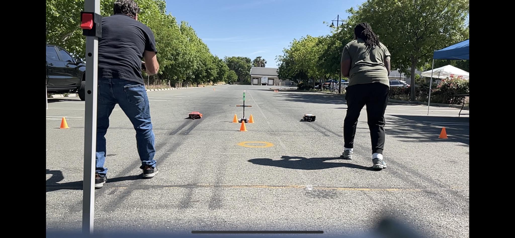
Starting Line Judge
DISCLAIMER: By using this hardware and software you do so at your own risk. You accept all risk and liability for any harm or damage that may occur during the proper or improper use of this product.

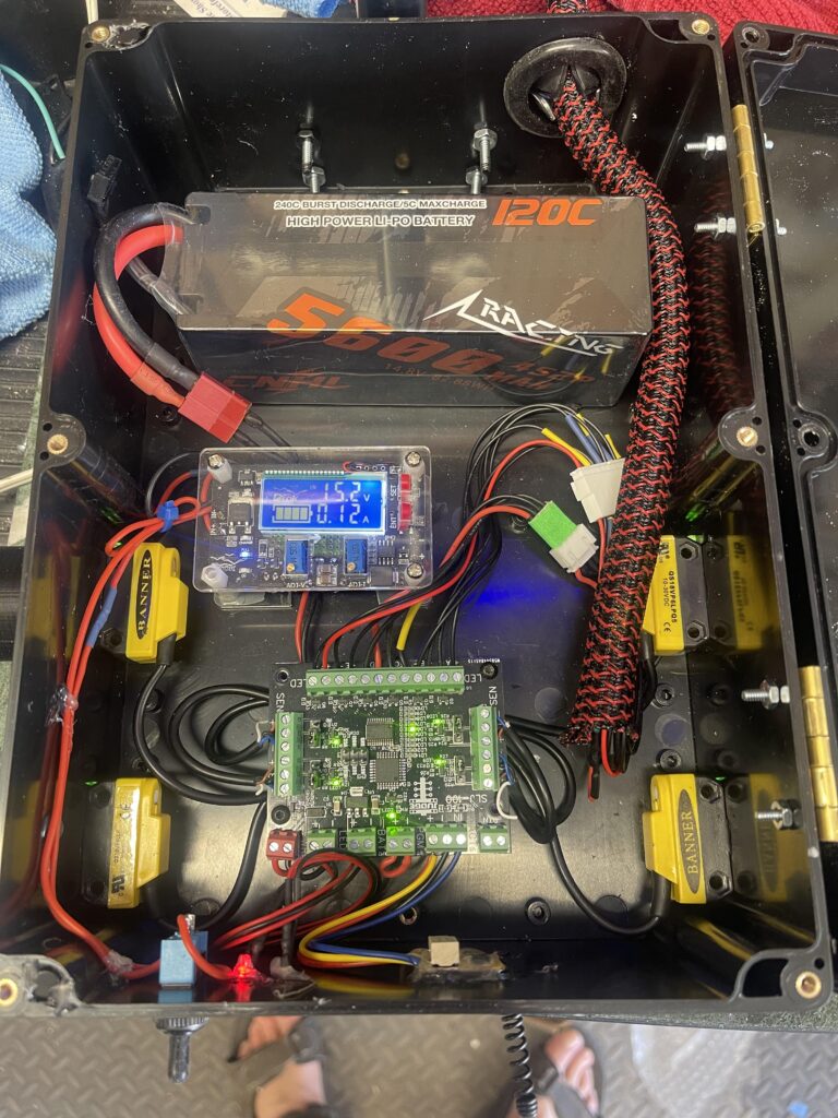
The SLJ is a DIY package consisting of only a logic board. It is the user’s responsibility to supply the other components and to assemble the system. The complete system functions as follows.
Alignment Mode: On initial power on alignment mode will be activated. While the system is in alignment mode the stage LEDs will flash back and forth indicating the presence alignment mode. The stage sensors’ alignment status will be indicated by the status of the green LEDs. The guard sensors’ alignment status will be indicated by the status of the red LEDs.
Following 10 seconds of constant alignment the system will exit alignment mode.
Normal Mode: System will wait for activation from one of the two activation inputs. Upon activation there is a random delay between 250ms and 1000ms, then the green light will be displayed. If the guard beam is broken during the staging procedure, prior to the system activation; the red bulb will come on to indicate the driver’s car is too far forward. If the guard beam is broken after the system is activated and prior to the random delay expiring, this will be considered a jump (red light/foul) and the red bulb will remain lit until the system is reset. Assuming no one jumps, both green bulbs will stay lit until the system is reset. At all times the yellow bulbs will indicate the status of the stage beams and will remain lit when the respective beam is broken.
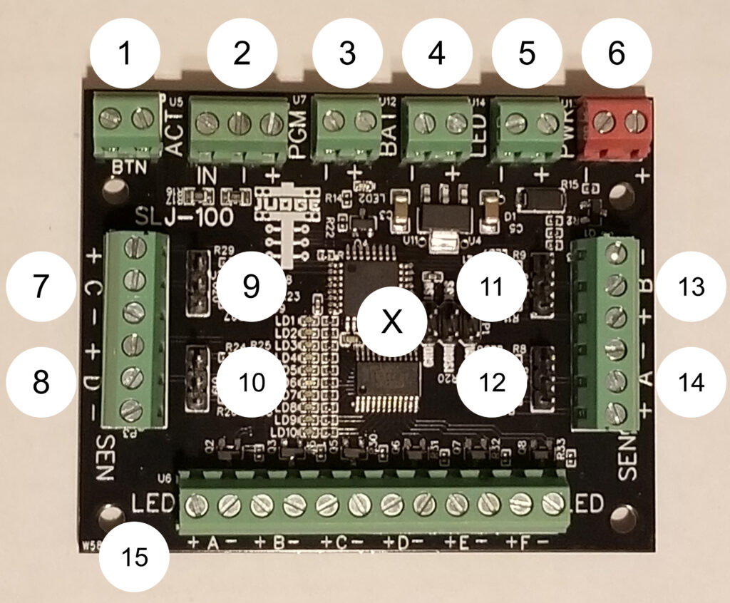
Overview – SLJ-100
| 1 | BTN: This input is the secondary activation input. This is designed to allow for a wired activation momentary button, in case the wireless fails. This input activates the system on the first press, then resets the system on the second press. |
| 2 | ACT: This input is the primary activation input. This is designed to allow for the use of wireless activation via a wirelessly activated relay. The IN terminal expects 12v to activate the input. The – and + terminals provide a ground and 12v. The system is activated when 12v is applied to the IN terminal, and deactivated then it is not present. The BTN input overrides the state of this input. |
| 3 | PGM: This input allows the use of Normally Closed (NC) or Normally Open (NO) sensors. All four sensors have to match either NC or NO. If your sensors are labeled NC then bridge the terminals by connecting a small piece of wire between them. Otherwise leave them open. |
| 4 | BAT: This output is meant to drive a 12v LED, to indicate low voltage. The LED will be turned on at approx. 10.2v. |
| 5 | LED: This output is meant to drive a 12v LED, to indicate the board is powered on. |
| 6 | PWR: This input is the primary power source to power the board and all connecting sensors and LEDs. The operational voltage range is somewhat dependent on the sensors and LEDs used, but the board will safely operate between 8.0 and 16.0 volts DC. |
| 7 | SENSOR_C: This three-wire input connects the left side guard sensor. |
| 8 | SENSOR_D: This three-wire input connects the left side stage sensor. |
| 9 | 3P-JUMPER: This three pin jumper allows for configuration of PNP or NPN. For NPN bridge the pins next to the “+” and “S”. For PNP bridge the pins next to the “-“ and “S”. This setting affects SENSOR_C only. |
| 10 | 3P-JUMPER: As of FLJ-100 this three pin jumper allows for configuration of PNP or NPN. For NPN bridge the pins next to the “+” and “S”. For PNP bridge the pins next to the “-“ and “S”. This setting affects SENSOR_D only. |
| 11 | 3P-JUMPER: This three pin jumper allows for configuration of PNP or NPN. For NPN bridge the pins next to the “+” and “S”. For PNP bridge the pins next to the “-“ and “S”. This setting affects SENSOR_B only. |
| 12 | 3P-JUMPER: This three pin jumper allows for configuration of PNP or NPN. For NPN bridge the pins next to the “+” and “S”. For PNP bridge the pins next to the “-“ and “S”. This setting affects SENSOR_A only. |
| 13 | SENSOR_B: This three-wire input connects the right side guard sensor. |
| 14 | SENSOR_A: This three-wire input connects the right side stage sensor. |
| 15 | LED: This output drives the tree LEDs. A=Left Stage/Yellow Bulb, B=Right Stage/Yellow Bulb, C=Left Green Bulb, D=Right Green Bulb, E=Left Red Bulb, F=Right Red Bulb |
| X | 6 PIN: This is the programming interface pins. This is not for end user connection. |
| Components Needed | |
| 4 | SENSORS: Any 12v DC compatible NO/NC PNP/NPN photoelectric sensor and its associated emitter or reflector. If you opt for a through-beam solution with an emitter and receiver, remember you will need to power the emitter. (https://www.amazon.com/gp/product/B07JMWCZ9B/) (https://www.bannerengineering.com/us/en/products/part.66454.html) (https://www.bannerengineering.com/us/en/products/part.42150.html) (https://baomain.com/products/e3f-r4n3) |
| 1 | ENCLOSURE: Box and Bang Light Tree (6 total bulbs) (Custom Built) |
| 8 | POWER SOURCE: Rechargeable 1.5v AA LiPos or some other 12v power source (https://www.amazon.com/EBL-Rechargeable-Lithium-Battery-Batteries/dp/B088ZN6XSJ/) (https://www.amazon.com/gp/product/B07WP1CYYW/) |
| 6 | 12v LED Lights Optionally of Three Different Colors to Indicate Stage, Start, and Jump/Foul (https://www.amazon.com/Clearance-Waterproof-Indicators-Wrangler-Silverado/dp/B09HWQ1KML/) |
| 1 | MOMENTARY BUTTON: Any standard two terminal/wire momentary push button (https://www.amazon.com/Parts-Express-Line-Button-Switch/dp/B07F935JY2/) |
| 1 | WIRELESSLY ACTIVATED RELAY: Latching relay (https://www.amazon.com/Universal-Wireless-Latching-Function-Industrial/dp/B0852G3KFJ/) |
Components Optional | |
| 2 | LED POWER/LOW VOLTAGE INDICATOR LIGHTS: Any 12v LED (https://www.amazon.com/Clearance-Waterproof-Indicators-Wrangler-Silverado/dp/B09HWQ1KML/) |
| 1 | POWER SWITCH: 12v DC Rated Toggle Switch, externally mounted, wired inline with power source positive to easily turn off power without opening enclosure. Also assists when aligning sensors. (https://www.amazon.com/gp/product/B07XC5KB8D/) |