Finish Line Judge
DISCLAIMER: By using this hardware and software you do so at your own risk. You accept all risk and liability for any harm or damage that may occur during the proper or improper use of this product.
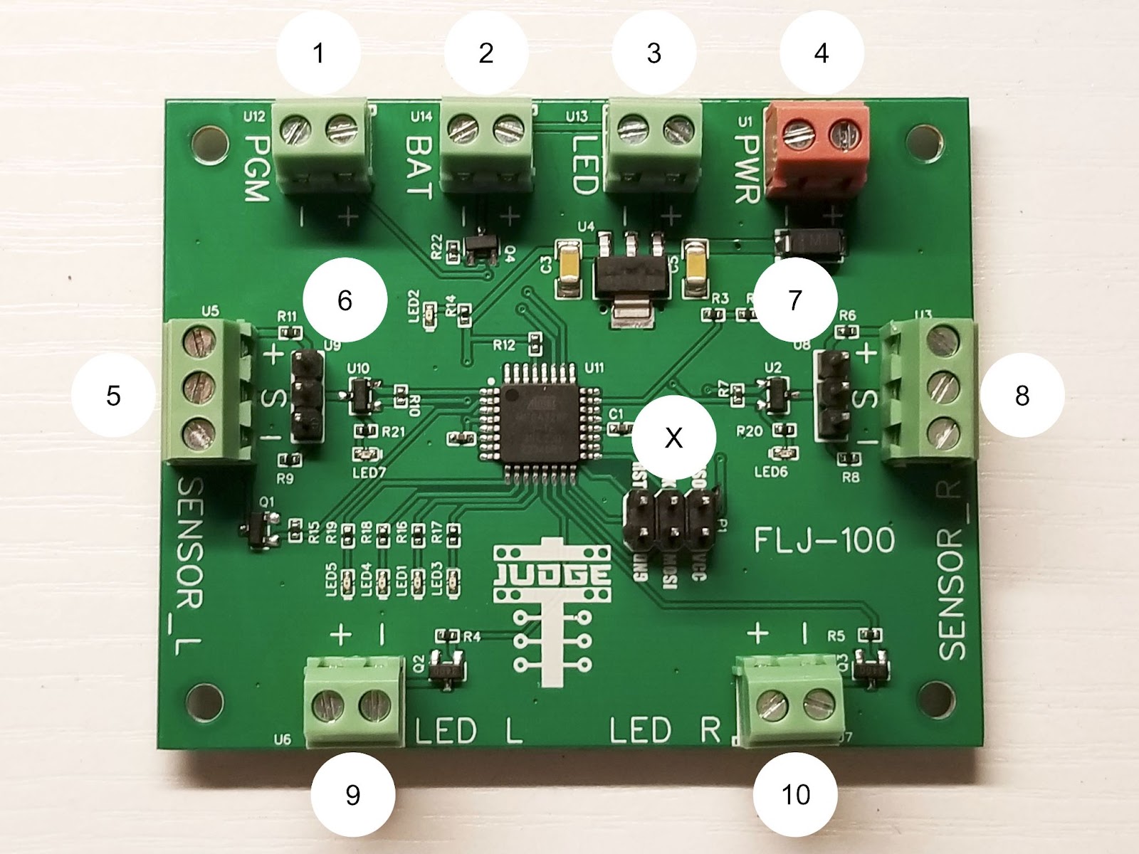
The FLJ is a DIY package consisting of only a logic board. It is the user’s responsibility to supply the other components and to assemble the system. The complete system functions as follows. Alignment Mode: On initial power on and if the system detects a sensor doesn’t reset, alignment mode will be activated. While the system is in alignment mode each lane’s win light LED will indicate the status of the sensor for that lane. If the LED is lit then the sensor is aligned and the beam is not broken. However, every 5 seconds the win light LEDs will go through a sequence to inform the user that the system is still in alignment mode. Following 10 seconds of constant alignment the system will exit alignment mode. Normal Mode: System will wait for one lane’s sensor beam to be broken and display that lane’s win light LED for 15 seconds. Then the system will reset and restart the cycle. Overview – FLJ-100 | |
| 1 | PGM: This input allows the use of Normally Closed (NC) or Normally Open (NO) sensors. Both sensors have to match either NC or NO. If your sensors are labeled NC then bridge the terminals by connecting a small piece of wire between them. Otherwise leave them open. |
| 2 | BAT: This output is meant to drive a 12v LED, to indicate low voltage. The LED will be turned on at approx. 10.2v. |
| 3 | LED: This output is meant to drive a 12v LED, to indicate the board is powered on. |
| 4 | PWR: This input is the primary power source to power the board and all connecting sensors and LEDs. The operational voltage range is somewhat dependent on the sensors and LEDs used, but the board will safely operate between 8.0 and 16.0 volts DC. |
| 5 | SENSOR_L: This three-wire input connects the left side sensor. |
| 6 | 3P-JUMPER: This three pin jumper allows for configuration of PNP or NPN. For NPN bridge the pins next to the “+” and “S”. For PNP bridge the pins next to the “-“ and “S”. This setting affects SENSOR_L only. |
| 7 | 3P-JUMPER: This three pin jumper allows for configuration of PNP or NPN. For NPN bridge the pins next to the “+” and “S”. For PNP bridge the pins next to the “-“ and “S”. This setting affects SENSOR_R only. |
| 8 | SENSOR_R: This three-wire input connects the right side sensor. |
| 9 | LED_L: This output drives the left lane win light LED. |
| 10 | LED_R: This output drives the right lane win light LED. |
| X | 6 PIN: This is the programming interface pins. This is not for end user connection. |
| Components Needed | |
| 2 | SENSORS: Any 12v DC compatible NO/NC PNP/NPN photoelectric sensor and its associated emitter or reflector. If you opt for a through-beam solution with an emitter and receiver, remember you will need to power the emitter. (https://www.amazon.com/gp/product/B07JMWCZ9B/) (https://www.bannerengineering.com/us/en/products/part.66454.html) (https://www.bannerengineering.com/us/en/products/part.42150.html) (https://baomain.com/products/e3f-r4n3) NOTE: If you decide to use the system to judge center line crosses you might consider the following receiver and its associated emitter.. (https://www.bannerengineering.com/us/en/products/part.71740.html) |
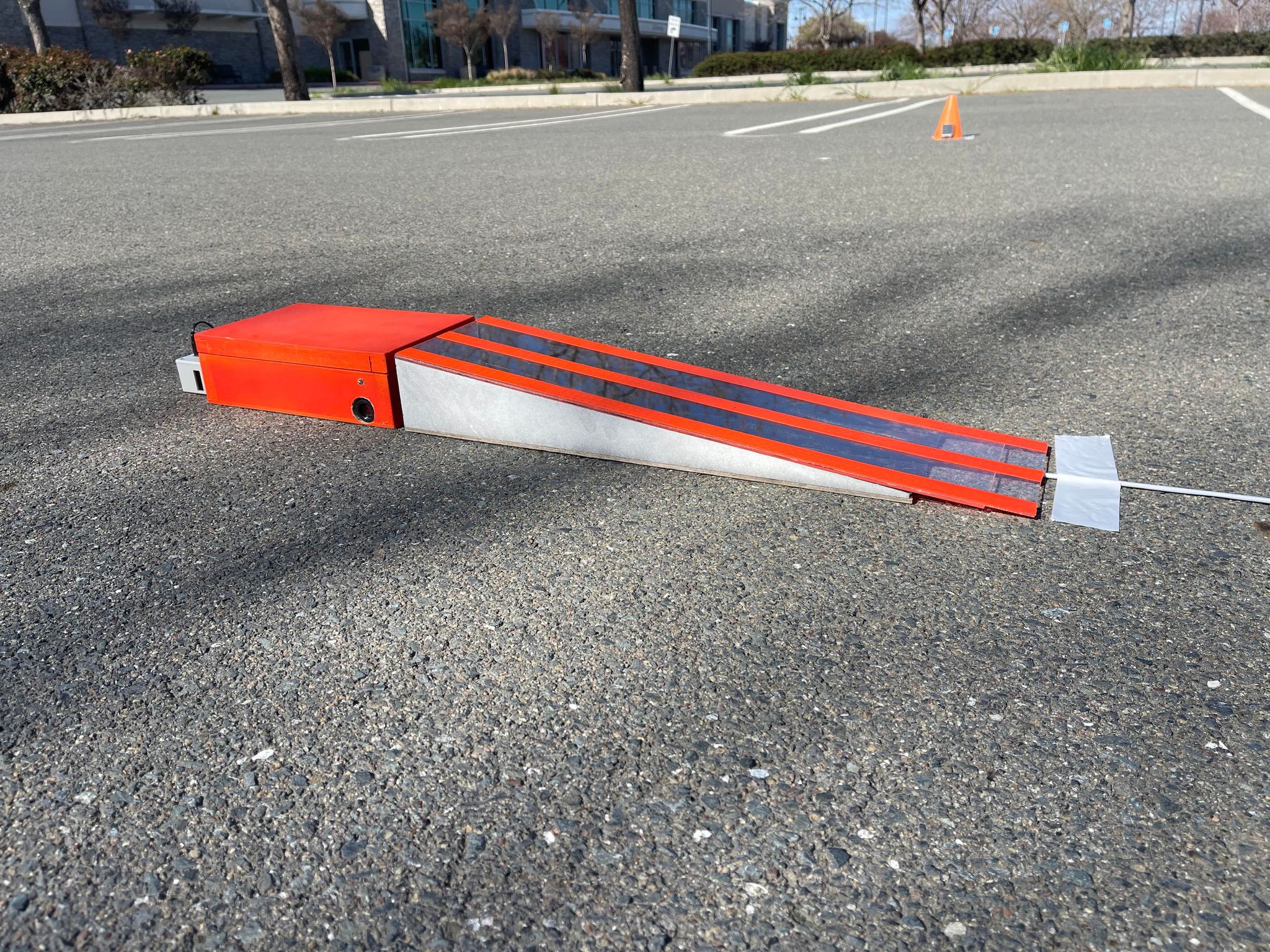
| 1 | ENCLOSURE: Box with Optional Ramp and Resistance Weight Area (Custom Built) |
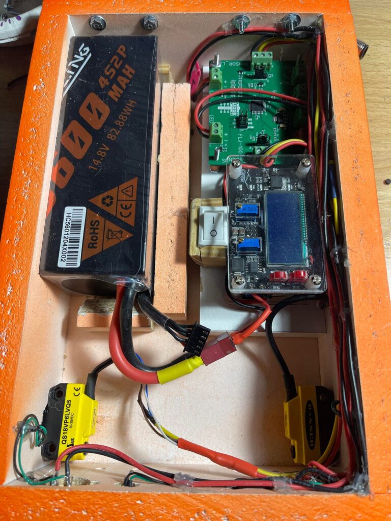
| 8 | POWER SOURCE: Rechargeable 1.5v AA LiPos or some other 12v power source (https://www.amazon.com/EBL-Rechargeable-Lithium-Battery-Batteries/dp/B088ZN6XSJ/) (https://www.amazon.com/gp/product/B07WP1CYYW/) |
| 2 | 12v LED Win Lights Optionally of Two Different Colors to Indicate Lanes (https://www.amazon.com/Clearance-Waterproof-Indicators-Wrangler-Silverado/dp/B09HWQ1KML/) |
Components Optional | |
| 2 | LED POWER/LOW VOLTAGE INDICATOR LIGHTS: Any 12v LED (https://www.amazon.com/Clearance-Waterproof-Indicators-Wrangler-Silverado/dp/B09HWQ1KML/) |
| 1 | POWER SWITCH: 12v DC Rated Toggle Switch, externally mounted, wired inline with power source positive to easily turn off power without opening enclosure. Also assists when aligning sensors. (https://www.amazon.com/gp/product/B07XC5KB8D/) |